A. Formulate Shape Function \( h(x) \)
Write \( h(x) \) as a quadratic equation.
\[ h(x) = a + b x + c x^2\]
Determine coefficients \( a \), \( b \) and \( c\) using the boundary conditions; We have three of them.
At \( x = 0 \) height is \( h_0 \), or: \( h(0) = a + (b \times 0) + ( c \times 0^2) = h_0\).
At \( {x = L} \) height is \({4}\)\({h_0} \), or: \( {h(L) = a + (b \times L) + (c \times L^2) =}\) \({4}\) \({h_0}\).
At \( {x = 0} \) the derivate of \( h(x) \) is zero, or: \(b + 2(c \times 0) = 0\).
Solve the above equations for \( a\), \(b\), and \(c\), we get: \(a = h_0 \), \( \; b = 0 \;\), \( c = \;\)\({3 h_0 / L^2}\)
Substituting the above values in the quadratic equation, we get:
\( h(x) = \)\( { h_0 (1 + 3 ({x \over L})^2 ) } \)
B. Write Moment of Inertia Function \( f(x) \)
The beam is assumed to have a rectangular cross-section, as shown below.

Then, its moment of inertia can be written in terms of x as: \(f(x) = b (h(x))^3/12\).
Substitute the expression for \( h(x) \) from Part A above in \( f(x) \) to get:
\( {f(x) = {{b h_0^3}\over{12}}(1 + 3{x^2 \over L^2})^3 } \)
Let \(I_0 = b h_0^3 /12 \), then \( f(x) \) can be written as:
\( {f(x) = I_0 (1 + 3{x^2 \over L^2})^3 } \)
C. Determine Beam End Rotations due to \( M_{ab}\)
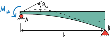
According to the Method of Virtual Work, we can write: \( \; \theta_{Ab} = \int {{M(x)m^*(x)}\over{EI}} dx \)
where \( M(x) \) is the equation for bending moment due to \( M_{ab}\),
\( m^*(x) \) is the bending moment equation due to a virtual unit moment placed at A in the direction of \( M_{ab} \),
\( E \) is the modulus of elasticity of the material (assumed to be constant), and
\( I \) is the moment of inertia of the beam which we expressed in Part B above as \( f(x)\).
To determine \( M(x) \), place a unit moment at A, as shown below.
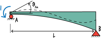
Then, calculate the support reactions:
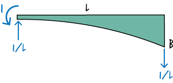
And write the moment equation for the beam:
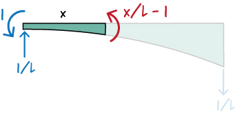
So, \( M(x) = M_{ab}(x/L - 1) \).
Further, from the above diagrams, we get: \( m^*(x) = x/L - 1\).
Therefore, we can write:
\[{ \theta_{Aa} = \int_0^L {{M_{ab}({x \over L}-1)({x \over L}-1)} \over {EI_0(1 + 3{x^2 \over L^2})^3}} dx }\]
And since \( M_{ab}\), \( E \), and \( I_0 \) are constant, then:
\[{ \theta_{Aa} = {M_{ab}\over{EI_0}} \int_0^L {{({x \over L}-1)({x \over L}-1)} \over {(1 + 3{x^2 \over L^2})^3}} dx }\]
To simplify the expression above, let \( \eta = x/L \). Then,
\[{ \theta_{Aa} = {M_{ab}\over{EI_0}} \int_0^L {{(\eta -1)(\eta - 1)} \over {(1 + 3{\eta}^2)^3}} dx }\]
Since \( x = \eta L\), then \( dx = L d\eta \), or
\[{ \theta_{Aa} = {M_{ab}\over{EI_0}}L \int_0^1 {{(\eta -1)(\eta - 1)} \over {(1 + 3{\eta}^2)^3}} d\eta }\]
Hence,
\[{ \theta_{Aa} = 0.21025{{M_{ab} L}\over{EI_0}}}\]
We can determine \( \theta_{Ba} \) in a similar manner.

Per the Virtual Work Method, we can write: \( \; \theta_{Ba} = \int {{M(x)m^*(x)}\over{EI}} dx \)
According to the above diagram, we want to determine the rotation at the right end of the beam when the load is applied at the left end.
Since the load remains the same, it is \( M_{ab} \), then we can use the same \( M(x) \) as above. So, \( M(x) = M_{ab}(x/L -1) \).
To determine \( m^*(x)\), place a virtual unit moment at B in the direction of the rotation, as shown below.
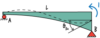
Now, draw the beam's free-body diagram and write the moment equation.
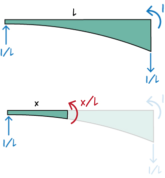
According to the diagram above, \( m^*(x) = x/L\). Then, we have:
\[{ \theta_{Ba} = {M_{ab}\over{EI_0}} \int_0^L {{({x \over L}-1)({x \over L})} \over {(1 + 3{x^2 \over L^2})^3}} dx }\]
Substitute \( \eta \) for \( x/L \) and \( L d\eta\) for \(dx\) in the above equation. And, change the upper limit of the integral from \( L \) to \( 1 \):
\[{ \theta_{Ba} = {M_{ab}\over{EI_0}}L \int_0^1 {{(\eta -1)(\eta)} \over {(1 + 3{\eta}^2)^3}} d\eta }\]
The above equation yields:
\[{ \theta_{Ba} = -0.047725{{M_{ab} L}\over{EI_0}}}\]
D. Determine Beam End Rotations due to \( M_{ba}\)
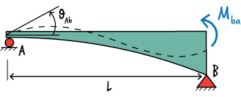
According to the Method of Virtual Work, \( \; \theta_{Ab} = \int {{M(x)m^*(x)}\over{EI}} dx \)
where \( M(x) \) is the equation for bending moment due to \( M_{ba}\),
\( m^*(x) \) is the bending moment equation due to a virtual unit moment placed at A in the direction of \( \theta_{Ab} \),
\( E \) is the modulus of elasticity of the material (assumed to be constant), and
\( I \) is the moment of inertia of the beam which we expressed in Part B above as \( f(x)\).
To determine \( M(x) \), start by placing a unit moment at B in the direction of \( M_{ba}\), as shown below.
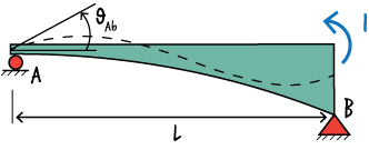
Then, write the moment equation for the beam.
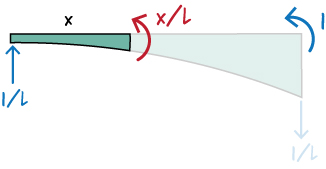
So, \( M(x) = M_{ba}(x/L) \). To determine \( m^*(x)\), place a unit moment at A in the direction of \( \theta_{Ab} \), then write the moment equation for the beam.
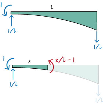
So, \(m^*(x) = x/L - 1 \). Now, write:
\[{ \theta_{Ab} = {M_{ba}\over{EI_0}} \int_0^L {{({x \over L})({x \over L}-1)} \over {(1 + 3{x^2 \over L^2})^3}} dx }\]
To simplify the expression above, let \( \eta = x/L \), and \( dx = L d\eta \). Then,
\[{ \theta_{Ab} = {M_{ba}\over{EI_0}}L \int_0^1 {{(\eta)(\eta - 1)} \over {(1 + 3{\eta}^2)^3}} d\eta }\]
Therefore,
\[{ \theta_{Ab} = 0.21025{{M_{ba} L}\over{EI_0}}}\]
We can determine \( \theta_{Bb} \) in a similar manner.
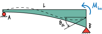
Using the diagram above, we can write: \( \; \theta_{Bb} = \int {{M(x)m^*(x)}\over{EI}} dx \)
\( M(x) \), bending moment equation due to \( M_{ba} \) has already been determined. It is: \( M(x) = M_{ba}(x/L) \).
To determine \( m^*(x)\), place a virtual unit moment at B in the direction of the rotation, as shown below.
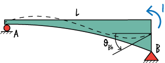
The free-body diagram for the beam is shown below.

Therefore, \( m^*(x) = x/L\). So, we can write:
\[{ \theta_{Bb} = {M_{ba}\over{EI_0}} \int_0^L {{({x \over L})({x \over L})} \over {(1 + 3{x^2 \over L^2})^3}} dx }\]
Substitute \( \eta \) for \( x/L \) and \( L d\eta\) for \(dx\) in the above equation. And, change the upper limit of the integral from \( L \) to \( 1 \):
\[{ \theta_{Bb} = {M_{ba}\over{EI_0}}L \int_0^1 {{(\eta)(\eta)} \over {(1 + 3{\eta}^2)^3}} d\eta }\]
The above equation yields:
\[{ \theta_{Bb} = 0.0304{{M_{ba} L}\over{EI_0}}}\]
E. Determine Beam End Rotations due to Applied load \( w \)
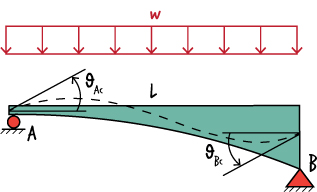
To determine , \( \theta_{Ac} \), we start from the general equation for the Virtual Work Method: \( \theta_{Ac} = \int {{M(x)m^*(x)}\over{EI}} dx \)
where \( M(x) \) is the equation for bending moment due to the distributed load,
\( m^*(x) \) is the bending moment equation due to a virtual unit moment placed at A in the direction of \( \theta_{Ac} \),
\( E \) is the modulus of elasticity of the material (assumed to be constant), and
\( I \) is the moment of inertia of the beam which we expressed in Part B above as \( f(x)\).
To determine \( M(x) \), we start by calculating the support reactions.
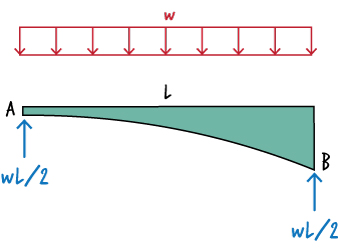
Then, write the moment equation for the beam.
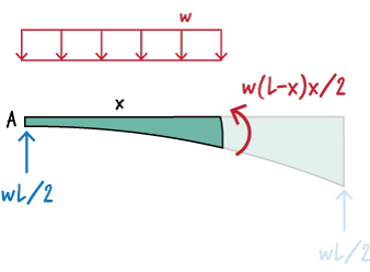
So, \( M(x) = w (L-x)x/2 \). To determine \( m^*(x)\), place a unit moment at A in the direction of \( \theta_{Ac} \), then write the moment equation for the beam.

So, \(m^*(x) = x/L - 1 \). Now, write:
\[{ \theta_{Ac} = {w\over{2EI_0}} \int_0^L {{(Lx-x^2)({x \over L}-1)} \over {(1 + 3{x^2 \over L^2})^3}} dx }\]
To simplify the expression above, let \( \eta = x/L \), \( \eta L = x\), and \( dx = L d\eta \). Then,
\[{ \theta_{Ac} = {w\over{2 EI_0}}L^3 \int_0^1 {{(\eta - {\eta}^2)(\eta - 1)} \over {(1 + 3{\eta}^2)^3}} d\eta }\]
Therefore,
\[{ \theta_{Ac} = -0.01648{{w L^3}\over{EI_0}}}\]
To determine \( \theta_{Bc} \), we start from: \( \; \theta_{Bc} = \int {{M(x)m^*(x)}\over{EI}} dx \).
We have already determined \( M(x) \), it is: \( M(x) = w (L-x)x/2 \). To determine \( m^*(x) \), place a virtual unit moment at B in the direction of \( \theta_{Bc} \)
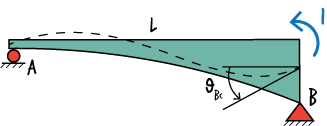
The free-body diagram for the beam is shown below.

Therefore, \( m^*(x) = x/L\). So, we can write:
\[{ \theta_{Bc} = {w\over{2 EI_0}} \int_0^L {{(Lx - x^2)({x \over L})} \over {(1 + 3{x^2 \over L^2})^3}} dx }\]
Or,
\[{ \theta_{Bc} = {w\over{2 EI_0}}L^3 \int_0^1 {{(\eta - {\eta}^2)(\eta)} \over {(1 + 3{\eta}^2)^3}} d\eta }\]
The above equation yields:
\[{ \theta_{Bc} = 0.0073875{{w L^3}\over{EI_0}}}\]
F. Write Total Beam End Rotations
To find the total rotation at A and B, add the individual rotations computed above.
\[ \theta_a = \theta_{Aa} + \theta_{Ab} + \theta_{Ac} \]
\[ \theta_b = \theta_{Ba} + \theta_{Bb} + \theta_{Bc} \]
Or,
\[{ \theta_{a} = 0.21025{{M_{ab}L}\over{EI_0}} - 0.047725 {{M_{ba}L}\over{EI_0}} -0.16475 {{wL^3}\over{EI_0}}}\]
\[{ \theta_{b} = -0.047725{{M_{ab}L}\over{EI_0}} + 0.03040 {{M_{ba}L}\over{EI_0}} + 0.0073875 {{wL^3}\over{EI_0}}}\]
Now, solve the above equations for \( M_{ab} \) and \( M_{ba} \). The solution, shown below, constitutes the slope-deflection equations for the tapered beam.
G. Slope-Deflection Equations for the Tapered Beam
\[{ M_{ab} = {{EI_0}\over{L}}( \theta_a + \theta_b) + {} w L^2 }\]
\[{ M_{ba} = {{EI_0}\over{L}}(\theta_a + \theta_b) - {} w L^2 }\]


