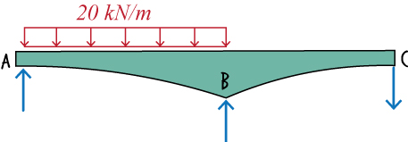
This interactive (javascript-based) web page is a part of Lecture SA58. The purpose of this web page is show how a change in the geometry of the beam
propagates through the formulation and changes the analysis results.
You can change the beam's geometry by moving the pin support thereby changing the length of each span and the height of the interior cross-section of the beam.
The distributed load is assumed to be acting on the left span, and the beam has a rectangular cross-section with
a variable height defined using a quadratic function.

\( 20 kN/m \)
\( h_0 \)
\( h_0 \)
\(4 h_0 \)
\( 9 m\)
\( 9 m \)


Drag the pin connection vertically to change the height. Drag it horizontally to change the span lengths. After a change has been made, see the analysis details and results below.
Source: Video Lecture SA58 and PDF notes.
A. Write Slope-Deflection Equations for the Left Span
Consider the tapered beam shown below.
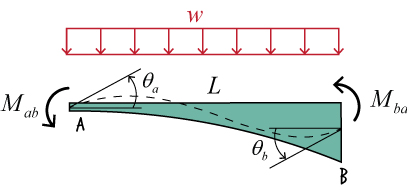
We derived the following slope-deflection equations for the above beam in an accompanying web page (see here).
This formulation assumes a rectangular cross-section for the beam with a height of \( h_0 \)
at the left end that increases to \(4 h_0 \) at the right end.
\[{ M_{ab} = {{EI_0}\over{L}}( \theta_a + \theta_b) + {} w L^2 }\]
\[{ M_{ba} = {{EI_0}\over{L}}(\theta_a + \theta_b) - {} w L^2 }\]
Where \(I_0\) is the moment of inertia of the beam's cross-section at the left end, and \(E\) is the
modulus of elasticity of the material.
Given that the left span of the bridge has a length of \(9 \; m\), and a uniformly
distributed load of \( 20 \; kN/m \) is placed on the segment (i.e., \(w = 20 \)), then the above equations simplify to:
\[{ M_{ab} = {{EI_0}\over{9}}( \theta_a + \theta_b) + 58.32 }\]
\[{ M_{ba} = {{EI_0}\over{9}}(\theta_a + \theta_b) - 301.32 }\]
B. Write Slope-Deflection Equations for the Right Span
Similar to the left span, the beam's right span is also tapered. Here however,
the beam segment tapers to the right; it is a flipped version of the left segment.
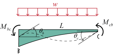
The slope-deflection equations for the above beam segment can be written as:
\[{ M_{ab} = {{EI_0}\over{L}}( \theta_a + \theta_b) + {} w L^2 }\]
\[{ M_{ba} = {{EI_0}\over{L}}(\theta_a + \theta_b) - {} w L^2 }\]
Since \(L = 9 \; m\) and \( w = 0 \), the above equations simplify to:
\[{ M_{ab} = {{EI_0}\over{L}}( \theta_a + \theta_b) + {} w L^2 }\]
\[{ M_{ba} = {{EI_0}\over{L}}(\theta_a + \theta_b) - {} w L^2 }\]
C. Write Joint Equilibrium Equations and Calculate Member-end Rotations
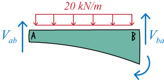
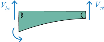
The free-body diagram of the left and right spans of the bridge are shown below. Note the joint equilibrium equations.
Having expressed the memeber-end moments in terms of joint rotations above, we can rewrite the joint equilibrium equations in terms of \( \theta_a \), \( \theta_b \), and \( \theta_c \).

The expanded equilibrium equations are:
\[{ field 36 }\]
\[{ field 37 }\]
\[{ field 38 }\]
Solve the above equations for the unknown joint rotations.
\[{ field 39 }\]
\[{ field 40 }\]
\[{ field 41 }\]
D. Determine Member-end Moments
Knowing the joint rotations, calculate the end moments using the slope-deflection equations.
For Segment AB, we have:
\[{ field 42}\]
\[{ field 43 }\]
Substituting the calculated rotations in the above equations, we get:
\[{ field 44}\]
\[{ field 45 }\]
For Segment BC, we have:
\[{ field 46}\]
\[{ field 47}\]
Upon proper substitution, the above equations yield:
\[{ field 48}\]
\[{ field 49}\]
E. Calculate Member-end Shear Forces
For Segment AB, we have:
\( 270 \; kN.m \)
\(12.5 m \)
Write the static equilibrium equations for the beam segment.
\[{ field 52}\]
\[{ field 53}\]
Solving the above equations for \(V_{ab}\) and \(V_{ba} \), we get:
\[{ field 54}\]
\[{ field 55}\]
\( 270 \; kN.m \)
\(12.5 m \)
The equilibrium equations for BC are:
\[{ field 52}\]
\[{ field 53}\]
We can determine the member-end shear forces by solving the above equations.
So, \(V_{bc}\) and \(V_{cb} \) are:
\[{ field 54}\]
\[{ field 55}\]
F. Determine the Support Reactions
Draw joints A, B and C, and show the member-end shear forces acting on them.
\( 34 \; kN \)
\( 12.8 \; kN \)
\( 12.8 \; kN \)
\( 12.8 \; kN \)
Since the sum of the forces in the y direction at each joint must be zero, then the support reactions are:
\( 12.8 \; kN \)
\( 12.8 \; kN \)
\( 12.8 \; kN \)


